Inter-VLAN Routing in Packet Tracer
Learn how to configure Inter-VLAN routing in Packet Tracer. This guide walks through creating VLANs, setting up a trunk link and configuring router subinterfaces.
This article will demonstrate how to configure Inter-VLAN routing between two or more VLANs on a network using 802.1Q trunks. At first we will brush up on the fundamentals of VLANs and trunks. You can jump to the demonstration in packet tracer here.
What is a VLAN?
A virtual LAN (VLAN) provides segmentation and organisational flexibility within a switched network. Devices connected to the same VLAN behave as if they were on the same physical network segment. Unlike traditional LANs, VLANs are based on logical rather than physical connections and operate as independant networks, even when sharing the same underlying infrastructure. Any switch port can be assigned to a VLAN.
A VLAN defines a logical broadcast domain that can span multiple physical network segements. By dividing a large network into smaller broadcast domains, VLANs reduce unnecessary traffic and improve overall performance. For example a layer 2 broadcast such as an ARP is only recieved by devices within the same VLAN, rather than by all devices on the entire network.
VLAN Trunks
VLAN trunks allow traffic to pass between switches, enabling all devices in the same VLAN but on different switches to communicate directly without requiring a router. A trunk is a point-to-point link between network devices that carries traffic for multiple VLANs accross the network.
Unlike an access port, a trunk is not assigned to a single VLAN. Instead, it acts as a shared link that transports traffic from multiple VLANs, typically tagging frames so the recieving device can identify which VLAN they belong to.

The highlighted links between the switches are configured to transmit traffic from VLAN 10 and 20 accross the network. This example network could not function without trunks.
VLAN Tagging
The standard ethernet frame header does not contain information about the VLAN from which the frame originates. Therefore when ethernet frames are placed on a trunk, this information needs to be added. This is called tagging and is accomplished with the use of the IEEE 802.1Q header (Standard IEEE 802.1Q). The header includes a 4-byte tag inserted wthin the original ethernet frame header.
When a switch revieves a frame on a port configured in access mode and assigned to a VLAN it inserts the tag in the frame header, recalculates the Frame Check Sequence (FCS) and sends the tagged frame out of the trunk port.
Tag Field
The VLAN Tag Control Information (TCI) field consists of a type field, a priority field, a Canonical Format Indicator (CFI), and a VLAN ID field. In the illustration below, the original Ethernet header is shown in blue, while the newly inserted 802.1Q tag is highlighted in green.

- Type: The tag protocol ID (TPID) value. This is set to hexadecimal 0x8100 for ethernet.
- User priority: Supports the level or service implementation.
- Canonical Format Identifier (CFI): Enables Token Ring frames to be carried accross ethernet links.
- VLAN ID (VID): The VLAN identification number that supports up to 4096 VLAN IDs.
Native VLANs
A native VLAN is the VLAN on a trunk link that carries untagged traffic. Frames sent without an 802.1Q tag are automatically associated with this VLAN. The IEEE 802.1Q standard defines a native VLAN for trunk links which defaults to VLAN 1 on cisco switches.
When a untagged frame arrives on a trunk port, it is assigned to the native VLAN. This is relevant because certain control and management traffic is sent untagged and therefore ends up in the native VLAN when traversing trunk links.
If no devices are assigned to the native VLAN, untagged frames can be unintentionally dropped, as there are no endpoints expecting the traffic. This can cause issues or make troubleshooting difficult if untagged traffic is not explicity accounted for in the network design.
Configuring VLANs
Cisco’s IOS knows two different types of VLANs. Normal Range VLANs which are identified with a VLAN ID between 1 and 1005 and whose configuration is stored in flash memory on the switch in a database file called vlan.dat. The VLAN trunking protocol (VTP) synchronizes the VLAN database between switches. The second type of VLAN are called Extended Range VLANs and are identified with VLAN IDs between 1006 and 4094. They support fewer VLAN features and require VTP transparent mode.
Next we will have a look at all the IOS commands needed for the demonstration in a later chapter.
VLAN creation
switch# configure terminalswitch(config)# vlan <vlan-id>switch(config-vlan)# name <vlan-name>switch(config-vlan)# endVLAN port assignment
switch# configure terminalswitch(config)# interface <interface-id>switch(config-if)# switchport mode accessswitch(config-if)# switchport access vlan <vlan-id>switch(config-if)# endTrunk configuration
switch# configure terminalswitch(config)# interface <interface-id>switch(config-if)# switchport mode trunkswitch(config-if)# switchport trunk native vlan <vlan-id>switch(config-if)# switchport trunk allowed vlan <vlan-list>switch(config-if)# endInter-VLAN Routing
VLANs segment switched layer 2 networks, this means that hosts on a VLAN cannot communicate with hosts on another VLAN unless there is a router or layer 3 switch to provide routing services. Inter-VLAN routing is the process of forwarding traffic from one VLAN to another.
Modern Inter-VLAN routing uses one physical ethernet interface to route traffic between multiple VLANs on a network. It’s called “Router on a stick” sometimes due to the network topology’s appearance. In order to make this possible the routers interface is configured using virtual software subinterfaces which identify routable VLANs. Each of these subinterfaces have their own IP address and VLAN assignment. When VLAN-tagged traffic enters the physical interface, it is forwarded to the corresponding subinterface. The router then determines the exit interface. If the exit interface is configured as an 802.1Q subinterface,, the data frames are VLAN-tagged with the new VLAN and sent back out of the physical interface.
Packet Tracer Demonstration
Now we will demonstrate how this works in Packet Tracer. If you want to follow along you can download the .pkt file using this link: inter-vlan-routing.pkt
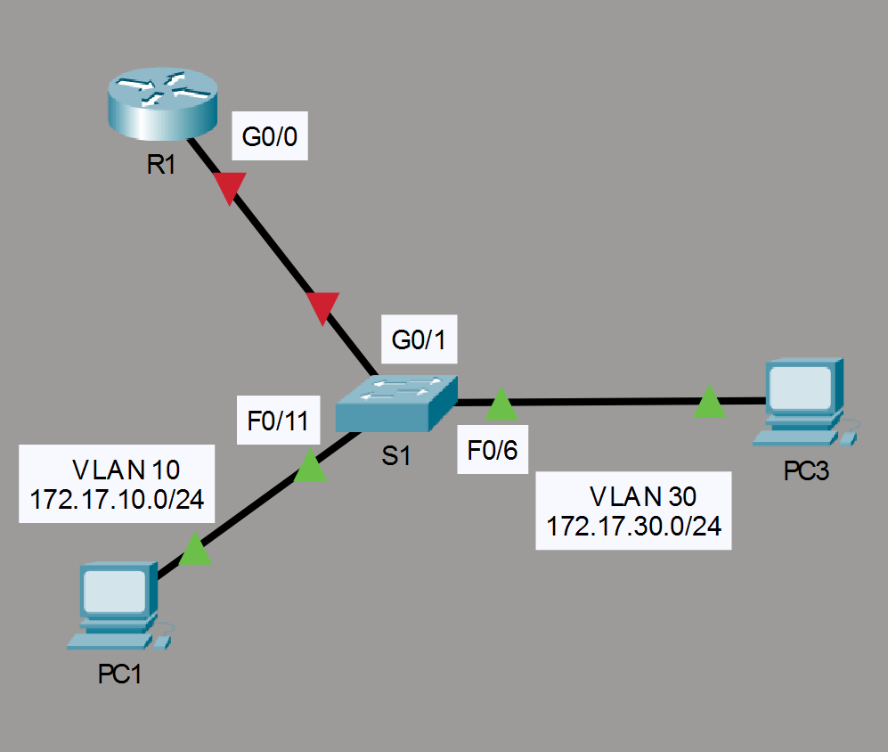
In our scenario we have two PCs connected to a switch. Currenty connectivity is broken and we will need to create the VLANs as seen in the image of the network toplogoy below. Once we have the VLANs we will configure the router with subinterfaces and then in the end we will configure the trunk on the switch. Let’s get started.
1. Create the VLANs
Select the switch in the center by clicking on it. A terminal will open where you will have to enter in order to be able to start typing. The first step is to Create the VLANs 10 and 30. We will start with VLAN 10 and then create VLAN 30 right after.
S1> enable
S1# config t
S1(config)# vlan 10
S1(config-vlan)# vlan 30
S1(config-vlan)# end
We can now verify that they were created using the show vlan brief command.
The next step is to assign the VLANs to the ports.
- Assign
F0/11as an access port and to VLAN 10 - Assign
F0/6as an access port and to VLAN 30
S1# config t
S1(config)# interface F0/11
S1(config-if)# switchport mode access
S1(config-if)# switchport access vlan 10
S1(config-if)# interface F0/6
S1(config-if)# switchport mode access
S1(config-if)# switchport access vlan 30
S1(config-if)# end
S1# show vlan brief
You should see the following lines.
10   VLAN0010                         active    Fa0/11
30   VLAN0030                         active    Fa0/6
2. Create the subinterfaces
The next step is to configure subinterfaces on the router using the 802.1Q encapsulation. In order to do this we need to create a subinterfaces on G0/0.
- Create a subinterface
G0/0.10and configure it with encapsulationdot1Qand the appropriate IP address - Create a subinterface
G0/0.30and configure it with encapsulationdot1Qand the appropriate IP address
R1> enable
R1# config t
R1(config)# int g0/0.10
R1(config-subif)# encapsulation dot1Q 10
R1(config-subif)# ip address 172.17.10.1 255.255.255.0
R1(config-subif)# int g0/0.30
R1(config-subif)# encapsulation dot1Q 30
R1(config-subif)# ip address 172.17.30.1 255.255.255.0
R1(config-subif)# end
Enable the interface G0/0.
R1# config t
R1(config)# int G0/0
R1(config-if)# no shutdown
R1(config-if)#
R1# show ip interface brief
You should see the following lines.
GigabitEthernet0/0.10  172.17.10.1     YES manual administratively up up
GigabitEthernet0/0.30  172.17.30.1     YES manual administratively up up
3. Enable trunking
The final step in order for the PCs in VLAN 10 and 30 to have connectivity is to enable trunking. In order to do so we need to configure the switch port connected to the router as a trunk.
S1> enable
S1# config t
S1(config)# int G0/1
S1(config-if)# switchport mode trunk
S1(config-if)# no shutdown
S1(config-if)# end
S1# show interface trunk
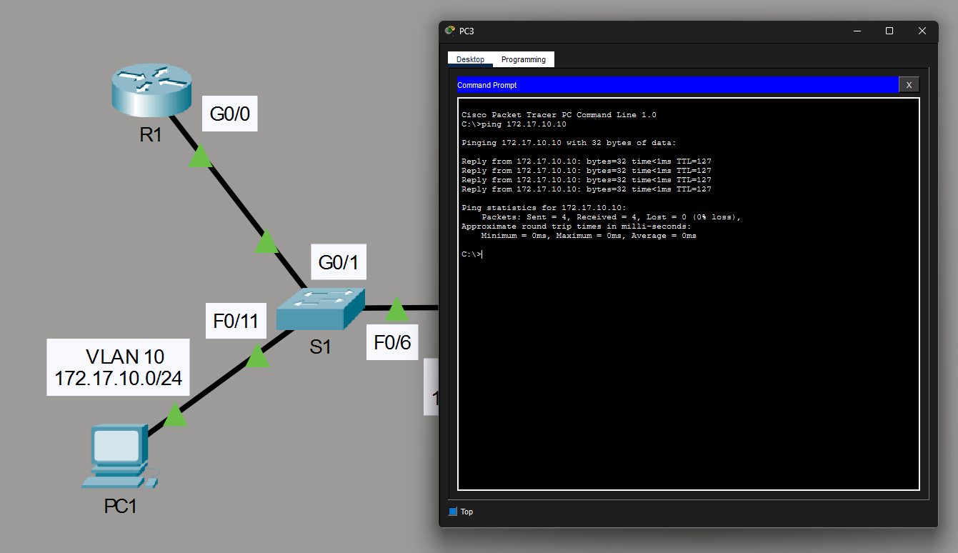
4. Testing with ping
Now both PCs can ping the default gateways and eachother. We have successfully configured Inter-VLAN Routing in Packet Tracer.